Old Mill Buildings Current Design Loads­ A Survival Approach

Cost benefits can be realized by modifying existing buildings compared with anew construction. The proposed analytical approach minimizes the reinforcement required toupgrade existing millbuildings without sacrificing currentstandards of safety, through optimization ofboth a building structural model and crane design loads.

Upgrading existing mill buildings is a high priority task. Companies are modifying their technology and facilities to increase production and reduce product cost. As significant cost benefit is realized with the modification of existing mill buildings and structures vs. new construction.

Mill building modification usually involves upgrading capacities of existing cranes or installation of additional cranes. This means that additional loads will be applied to the existing structures which have to be checked for the new load conditions and brought into compliance with requirements of presently active design codes.

Design work associated with upgrading existing g mill buildings, especially old mill buildings, presents a challenge for the design engineer. Old mill buildings are considered in this article as those designed prior to 1969, when the first edition of the Guide for the Design and Construction of Mill Buildings, AISE Technical Report No. 13 was published. (The first edition of AISE Technical Report No. 13 and the subsequent, second edition, 1979, contain the current recommendations for steel mill building design loads and load combinations.)

Design codes and techniques (structure modeling, determination, application and distribution of design loads) used in the past have changed significantly. Design codes presently used (eg, AISC, AISE and others) establish various design criteria, many of which were not (or only partially) recognized in the original design of existing mill buildings.

Currently, it is common for the design engineer to encounter significantly overstressed conditions when current design criteria are applied to existing mill buildings and their original cranes. However, many of these buildings have performed satisfactorily for many years and do not show any sign of distress in the regions that have been theoretically over­ stressed during that time. In such cases, modification of existing mill buildings to handle additional crane load. could require a substantial reinforcement with an associated long downtime period    for the   mill operation and large capital expenses. Such decisions could make a modification project economically unacceptable.

The following inequality defines the theoretical overstress condition in terms of the allowable stress design (ASD) method.
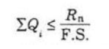
 

The left side of the inequality is the required strength (design forces or moments) which is a function of loads and the design model of the structure. The right side of the inequality is the allowable strength which is the nominal strength divided by factor of safety. When the two sides of the inequality are divided by the appropriate section property (eg, are or section modulus), the inequality is converted into a relationship between design and allowable stresses. The theoretical over­ stress is a condition when the design stress is greater than the allowable stress. To eliminate the theoretical overstress situation, the design engineer could use one of the following techniques separately or in combination:

  • Reduce safety factor.
  • Increase section properties.
  • Improve design model of building.
  • Review and revise design loads and combinations.

Reducing the safety factor is difficult for the designer unless it can be proven that the particular loading combination that creates the overstress condition has a low probability of occurrence and/or a short duration of action (similar to combinations which include wind or earthquake loads). This approach is undesirable because the design.er will go against a common tendency to increase the required safety factor for old structures.

Increasing the section properties of the structure means reinforcement.

Improving the design model of the building has the objective of obtaining more realistic load distributions which would be expected to lead to a design force reduction. Changing the building design model could require some modifications in the real structure that are less expensive and more convenient to perform than direct reinforcement of the overstressed members. Some design loads and combinations recommended by cur­ rent design codes are unduly conservative, especially loads generated by the crane or trolley motion. Some land combinations recommended by design codes include at least two instantaneous impact type loads with a probability of coincidence close to zero. Such combinations, after approval 

by the mill building owner, can be excluded from consideration or used with a substantially reduced safety factor.

Optimal structural design of mill building modifications should minimize the total cost of the project. The project cost consists of a direct cost of building modifications and losses associated with downtime in the mill operation required to accomplish the modification.

An advanced structural model and critical review of crane loads and load combinations can help achieve the optimal design in existing mill building modification projects.

Historical Review of Mill Building Design Models

In early days, designers did not have the benefit of the knowledge which   extensive research and computerized analysis provide today and, instead, had to depend of common sense. Because designers had no practical means of dealing with indeterminate building structures, they made the structures statically determinate by assuming pinned ends and designing columns and trusses as simple elastic structures. At the beginning of the 20th century, Ketchum12 proposed solutions for statically indeterminate mill building frames. Utilizing Ketchum's formula, the designer was able to analyze the building as a statically determinate planar frame.

For many years, Ketchum's book on steel mill building design were the only textbooks for students and the handbooks for design engineers. Many mill buildings were built using his recommendations and many are still providing dependable service. However, analysis of these buildings using present design codes predicts significant overstressed conditions, mainly due to increased design load factors.

In 1956, Murray described a new approach in mill building design called the space frame concept3. Murray proposed two different models for mill building frame design: Model No. 1, for and roof loads and Model No. 2, free to sway frame, for wind loads. In Model No. 1, the crane column was taken out of the space frame and analyzed as a free body or isolated member. The column was considered as fixed at the base and pinned at a point midway between the knee-brace and the bottom chord of the roof truss. No side sway of the pin was allowed. Utilization of the Murray approach provided more economical mill building column design in comparison with the plane frame model. However, all buildings experience side sway. The side sway may be small for multi-bay stiff buildings with well developed bottom chord bracing or it may be large in tall, 1 or 2-bay flexible buildings. Large side sway also occurs at building end bents and at bents located next to temperature expansion joints. The Murray single-column model neglects the side sway effect. This results in underloading of the lower part of the column and overloading of the upper part due to crane loads in comparison with a contemporary 3-D building model which includes side sway provisions.

In summary, mill buildings designed prior to the late 1950's were most likely designed as plane framed structures. Strong columns and weak bottom chord bracing are typical features of these buildings. Changing the building model from a plane into a space frame allows for crane load sharing. Such a model change would require modification of the bottom chord bracing and probably a few minor column modifications.

Mill buildings designed after the late 1950's may have been designed as a plane frame, but with much stronger bottom chord bracing. The possibility exists that a particular mill building design was based on the Murray space frame concept. In this case, the designer faces a difficult problem to bring the existing building into compliance with the current design codes without significant reinforcement and/or rationalizing design loads and combinations.

Computer Modeling of Mill Building Frame

It is now commonly accepted that mill buildings are space structures.

Crane runway girders deliver crane loads directly to two or three transverse bents simultaneously (Fig. 1). These localized crane forces are then distributed from the loaded bents in the form of reactive forces to adjacent transverse bents through horizontal diaphragms (eg, bottom chord horizontal bracing, floors, etc). In this transaction, the crane acts as a rigid link between two sides of the runway.

It is possible to develop an elastic 3-D finite element computer model of a mill building. However, such a model, even for a mid-sized mill building, could easily consist of a few thousand nodes and elements (Fig. 2). Many design companies are not equipped with computers and programs to perform such an analysis. In addition, it is inconvenient to work with a large program when many changes can be expected before the final solution is obtained.

An alternative approach, which provides a high degree of accuracy, is to resolve the 3-D mill building frame problem into 2-0 problems using a series of 2-D stiffness computer analyses (Fig. 3).

Each transverse bent is modeled as a planar frame. Interaction between bents is provided by a horizontal diaphragm (roof truss bottom chord bracing or floor framing) which is considered as a horizontal continuous frame on a series of elastic supports with linear elastic stiffnesses equal to the lateral stiffnesses of the transverse bents at the level of the horizontal diaphragm. Reactive forces from crane-loaded bents at the horizontal diaphragm level are distributed by the horizontal diaphragm between all bents which are used as elastic supports for the diaphragm. The solution can be formulated as a sequence of steps (Fig. 3):

  • Step No. 1 - Develop a planar model of each transverse bent and apply horizontal load T = 1 kip at the horizontal diaphragm level (the bottom chord bracing in the example). Run the analysis and determine the frame horizontal displacement at this level. The reciprocal of this displacement is a linear elastic spring constant for the horizontal diaphragm support. Prior to Step No. 2, the design crane loads (vertical and horizontal) have to be determined for the analyzed and adjacent bents (Fig. 1).         .
  •  Step No. 2 - Place a horizontal support (vertical roller) at the horizontal diaphragm level into each plane frame model of the transverse bents subject to crane loads. Determine the horizontal reaction Rn at these supports due to the crane loads only.
  • Step No. 3 -Develop a planar model of the horizontal bottom chord bracing on elastic supports. Sometimes, the continuity of the bottom chord bracing is interrupted by repair bays or temperature expansion joints. In such cases, the longitudinal spread of the space frame is defined by the continuity of the existing or modified bottom chord bracing. To ensure load sharing, bottom chord bracing must bracing must be stiff enough to transfer loads. Tension rods (often with large sag) should be replaced with angles or tees. Apply horizontal reactions from Step No. 2 to the bot tom chord model as external forces and determine the react ions at all elastic supports. These reactions will show the distribution of crane loads between transverse bents.
  • Step No. 4 - Remove the vertical roller (Step No. 2) from the planar model of the bent. Apply an external reactive force at this point equal to Rn. - rn. as determined in Step No. 3 for the crane loading of interest. The bent is now modeled as a planar, free to sway, frame with an external reactive force at the bottom chord bracing lev el which represents the resistance of the entire space frame to sway motion of a single frame. This is the space frame sharing effect, which helps to substantially reduce column bending moments   in comparison with simple free to sway mill building frames. The effect of the crane side thrust distribution using different frame models is shown in Fig. 4.

The degree of load sharing varies and depends on the relative stiffness of the bracing to the bents and position of the analyzed bent in the space frame.

Prior to analyzing an existing mill building using the 3-D concept, the designer should perform the planar, free to sway, frame analysis of the original building frame and determine the need for column reinforcement. The designer should then decide whether the bottom chord modification is required to change the building design model. (The author has  experienced cases when the existing building columns being analyzed as part of a planar frame, satisfactorily resisted the current design load and, thus, required no modifications.)

Evaluation of Crane Loads

All overhead traveling cranes operate dynamically, simultaneously generating and being under the action of forces which include steady-state and time-varying components.

The steady-state part of the total crane loads is represented by the static loads such as the weight of the crane bridge, trolley, lifting mechanism, other equipment and the lifted load. At each moment of crane operation, the s ta tic crane wheel loads can be determined by applying the laws of statics. Dynamic forces are time varying in direction and/or magnitude. Crane dynamic loads are introduced by the crane work and by the inertia 

of the masses, which are put in to motion. The crane operation generates forces due to load lifting, trolleying, crane travel and friction. The inertia forces are those that result from overcoming the inertia of the load and crane component masses in acceleration and deceleration processes for all functional motions.

For any defined condition, the crane dynamic forces can be calculated with reasonable accuracy, but it is seldom possible to define the operating condition accurately. This is especially true for the dynamic forces in a coupled system such as a mill building/crane. Interaction between the building and crane develops through the runway, crane rails and crane wheels, which makes the analytical definition of the system relatively complicated. Apparently, this is the reason why no adequate methods of describing crane dynamic forces have been developed since the first mill buildings were designed.

Current design codes define crane dynamic farce! as a per­ centage or factors of known static loads such as lifted load, trolley and bridge weight, wheel load, etc. A similar approach was used by Ketchum at the beginning the century in the General Specifications for Steel Frame Mill Buildings.

Dynamic forces determined by using design code recommendations do not reproduce a reasonable approximation of the actual forces because they do not include in their determination such variables as motion characteristics of the crane and its components and the stiffness of the crane runway support structures. This can be demonstrated by the following example.

Example of Dynamic Calculations

Dynamic forces have been determined swing different design code requirements and simplified dynamic analyses based on the stiffness and motion characteristics of the crane and building. The simplified dynamic analyses included a few assumptions: all vertical and horizontal (from straight side thrust) wheel loads were equal on one crane side; and the lateral stiffnesses of the crane girders were not taken into account. Longitudinal horizontal dynamic forces were not included in the example because of the simplicity of their determination. These forces cannot exceed the sum of crane traction forces which equal the vertical loads on drive wheels times the coefficient of static friction for steel on steel, or the crane runway stop collision force.

A 250-ton ladle crane, positioned to produce the maximum column load, was used.

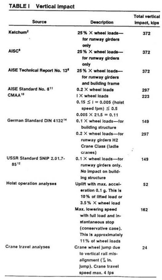
Vertical impact - Vertical impact forces result from crane longitudinal travel and hoisting operations. The variety of crane vertical impact forces determined for the same crane using different design sources is illustrated in Table I. Several tests performed on mill cranes5.15 show that impact during real operating conditions did not exceed 7% of the crane static loads.

It is difficult to develop a realistic analytical model or simulate a test load condition that results in a 25% impact factor for crane loads. A drop-off 

load case should be excluded as nonrealistic. Griggs5 proposed that this conservative design impact factor should be called an overload factor rather than a dynamic impact factor.

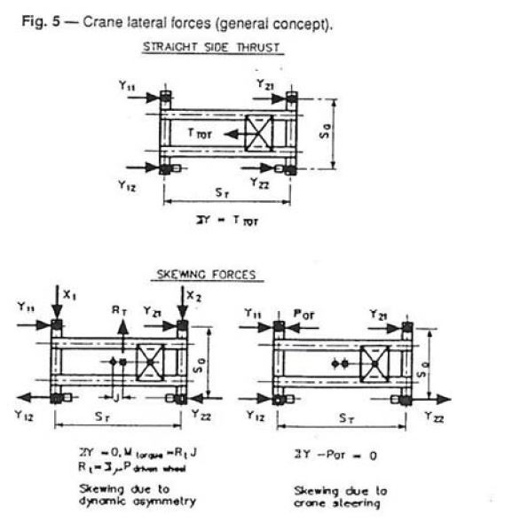
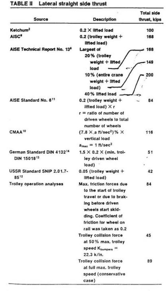
Lateral side thrust - Lateral crane  straight   side  thrust forces (Fig. 5) are the result of trolley operations: acceleration or deceleration; friction forces due  to start of trolley travel or braking; and collision with the trolley stop. The straight side thrust force for the 250-ton ladle crane based on various design sources is shown in Table II.


There is a noticeable nonconformity between two AISE documents, Technical Report No. 13 and Standard No. 6, in the determination of lateral side thrust forces (Table II). In reality, the forces applied by the crane to the runway are equal to the reactive forces from the runway to the crane. 

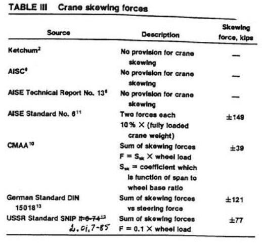
Skewing forces - Crane skewing forces are the least investigated dynamic forces (Fig. 5). These forces originate from the tendency of the crane to meander as it travels in the longitudinal direction. The reason   for such a movement is dynamic asymmetry which generates different traction forces on the two sides of the  runway, imperfections in cranes and evaluation of skewing forces can be found in references 13 and 16. Skewing forces determined for the 250-ton ladle crane based on various design sources are shown in Table III. 

Crane skewing forces always provide a local horizontal bending for craneway girders and building columns. They only generate a horizontal twist on the overall space frame of the building. (Only space frame analyses could provide accurate distribution for the frame forces due to crane skewing.)

The lateral loads from crane skewing could be more unfavorable than the lateral loads from trolley operations for crane girders and their connections to columns. The probability of the peak magnitudes of the trolley lateral forces and the crane skewing occurring simultaneously is practically zero.

The absence of a crane skewing force provision in AISE Technical Report No. 13 and AISC specifications9, and excessively high, straight side thrust forces in comparison with other design codes, suggests that the skewing force provision is built into the total side thrust force. Such an approach creates an excessively conservative design case for the building frame analysis.

It appears that no one (at least in the U.S. and Canada) has measured crane skewing forces.

During the last few years, two field tests were performed in the U.S. and Canada on steel mill plants. The magnitudes of vertical impact and lateral side thrust forces determined using test results were substantially below the same forces determined in accordance with the AISE Technical Report No. 13 and the AISC specification9. The results of these tests were successfully used in the projects of upgrading the existing steel mill plants. 

At the present time, in the absence of rational methods for crane dynamic force determination recommended by the design codes, there are two basic alternatives  which can be exercised by the design engineer in cooperation with the steel mill owner to determine realistic crane forces  for the particular crane and building, an analytical and a field test method.

In the analytical method, crane dynamic forces should be determined by dynamic analyses using motion and stiffness characteristics of the crane and the building.

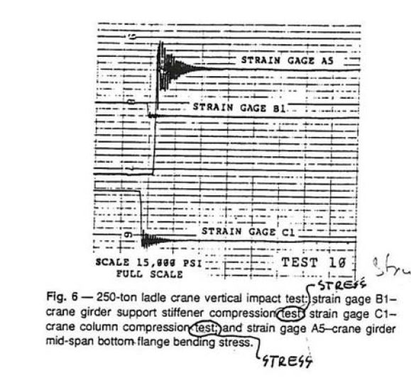
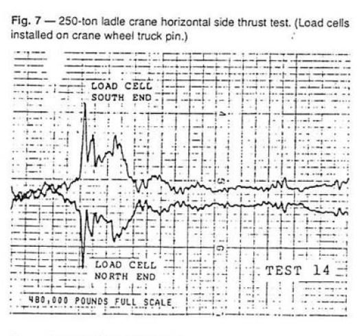
In the field test method, the most severe crane operation conditions should be simulated to produce the maximum impact and side thrust forces. The system of strain gages installed on the crane girders and the crane makes it possible to determine the stress fluctuation due to various crane actions producing dynamic forces. The recorded stresses then can be transformed into forces which caused these stresses. The second method is more precise because it eliminates all analytical assumptions which cannot be avoided in the first method. The cost of the field test will be easily recovered later by savings received from the elimination or reduction in the building reinforcement and downtime required to perform the reinforcement.

Load Combinations

Engineering judgment is required in selecting realistic load combinations , especially when the designer deals with an existing mill building. The goal is to include in each load combination only those loads that can be reasonably expected to occur simultaneously. In addition to static vertical loads, crane loads include a group of instantaneous dynamic loads; vertical impact; horizontal longitudinal forces; horizontal straight side thrust; and horizontal skewing forces. Considering more than one of these instantaneous dynamic forces at their peak value in one load combination creates a load case with a low probability of occurrence. The instantaneous character of vertical impact and side thrust forces is illustrated in Fig. 6 and 7.

To determine the probability of simultaneous occurrence of two or more instantaneous dynamic forces, it is necessary to take into account various other parameters. These include the position of the crane bridge,  position of the  trolley and the percentage of maximum load being lifted  at  any time. For a given structural member under consideration there is only one combination of these three parameters, out of an infinite number of combinations, that results in the maximum required strength.

Current design codes select this single combination of crane bridge and trolley position along with 100% of maximum lifted load to which several instantaneous dynamic factors are then applied. Commonsense dictates that the greater the number of parameters, which can vary, the lower is the probability that anyone combination may occur. Especially, when several parameters are instantaneous.

AISE Technical Report No.13 Guide for Design and Construction of Mill Buildings was developed by engineers working for the steel industry reflects, at least judgmentally, the operation of steel mill cranes. This explains why the majority of steel mill owners in their specifications for upgrading existing mill buildings require compliance with this document. This is a difficult problem because in addition to conservative crane loads, the report recommends the use of excessively conservative load combinations with a probability of occurrence close to zero. This conservatism regarding crane dynamic loads can be considered as a defensive measure against some abusive usage of cranes and/or improper maintenance of cranes and craneway. However, it is difficult to explain conservative load combinations that combine already conservative loads to create an extremely conservative solution. Such an approach is not economically feasible for the upgrading of existing mill buildings.

A new, revised edition of AISE Technical Report No. 13, which will be issued in 1991, includes a new Supplement II Suggested Procedure for Inspecting and Upgrading of Existing Structures. Supplement II contains valuable recommendations concerning the upgrading of existing mill buildings. This revised edition recognizes that recommended crane runway loading requirements may be somewhat conservative and encourages the designer to exercise engineering judgment in the analysis of existing structures.

The design engineer, in consultation with the steel mill owner, should develop load combinations that meet the specific criteria of a particular plant operation.

The author would recommend the exclusion of any combination of instantaneous dynamic crane loads which originate from different functional processes. Examples include: hoist operation and trolley travel; crane and trolley travel; hoist operation and crane travel; trolley bumper collision and hoist operation; etc.

The following suggestions are based on a review of original and current U.S. and some foreign structural design codes, technical literature and more than 25 years of the author's experience of various industrial projects

  • Dynamic load, due to vertical impact should not be combined with any other crane dynamic loads. A 25% vertical impact factor should be included only in crane girder, and their connection to column analysis to vertical impact should be used in fatigue analyses of crane runway girders. The vertical impact factor used in framing analyses (one   crane case) should be eliminated or reduced. The magnitude of the reduced impact factor should be not more than 10% of the crane static loads.
  • The straight side thrust and skewing forces should be considered in separate load combinations.
  • Longitudinal crane dynamic forces can be considered separately from other crane dynamic forces or can be considered as part of the skewing force case.

Simultaneous occurrence of maximum vertical load from more than two cranes in the vicinity of one column (eg, two cranes in each adjacent aisle) and dynamic loads from one crane has a low probability of occurrence. In such a case, the total crane vertical loads from more than two cranes should be reduced by using an appropriate reduction load factor (Example: USSR, S NiP 2.01.7-85 uses a factor of 0.8).

  • If several crane dynamic loads at their peak values are combined in one load case (eg, vertical impact and straight side thrust, straight side thrust and skewing, etc), 1he allowable stresses should be increased by 33%, similar to load cases that include wind and seismic

Separation of crane dynamic loads into different load combinations should produce a substantial increase in load combinations. This should not be considered a problem since present computer programs could provide a force envelope (maximum and minimum forces from all load combinations) for each framing member.

Exclusion of unrealistic loading cases from structural analysis of existing mill buildings does not require any sacrifice of present safety standards but creates an opportunity to develop an effective upgrading project.

Conclusions and summary

One experienced engineer wrote that the design of a mill building is 90% judgment and 10% perspiration.  While the exact percentages are debatable, especially for upgrading existing mill building, sound engineering judgment should form an important part of the structural design for the upgrade of existing mill buildings.

Some basic questions that must be resolved by the design engineer are:

  • What building design model best fits the existing structure? What minor frame modifications can be implemented to change the behavior of an existing structure to minimize or eliminate member reinforcement?
  • How should crane runway girders with restrained supports and knee braces be treated? Remove, neglect or consider the knee brace effect on girders and columns. What should be done with fatigue sensitive details? Fix them or monitor them and see what hap-pens?
  • How to create load combinations that will include all possible realistic loads occurring simultaneously? How many instantaneous crane dynamic forces should be included in one load combination? How to consider the probability of simultaneous maximum loads from several cranes working in the vicinity of a particular column?

All these and many other questions (omitted from this article) have to be answered by the design engineer and approved by the steel mill owner prior to de tailed analyses and design.

A mill building modification project will inevitably require the solution of many problems which were not discussed in this article. Even for the problems which were discussed, there is no direct and clear solution. In all stages of the project, the design engineer should continuously use sound engineering judgment to achieve the best results. 

Two important parts of the structural design of mill buildings have been considered; building modeling and crane loads. Each of these subjects requires further development and improvement. Accurate methods of crane load determination and better understanding of soil-structure interaction should help in the future development of more rational criteria for mill building design.

Since 1980 the design approach presented has been successfully used in numerous steel mill modification projects in the US and Canada. Implementation of this approach resulted in achieving a reliable building   modification with minimum cost required to perform it.

REFERENCES

  1. Ketchum.  M S., Design of Steel Mill Buildings, 5th ed., McGraw-Hill, New York. 1932.
  2. Ketchum, M. S., Structural Engineering Handbook 3rd ed.. McGraw-Hill. New York, 1924.
  3. Murray, J. J ., and Graham, T. C., "The Design of Mill Buildings," AISE Yearly Proceedings , 1957, pp 191-204.
  4. Rabinavitch. I. M., Fundamentals of Structural Mechanical (in Russian) USSR. Moscow, 1956.
  5. Griggs, P. H., "Mill Building Structures." Paper presented at Canadian Structural Engineering Conference, 1976.
  6. Streletsky. H., Steel Structure, (in Russian) USSR, Moscow, 1965.
  7. Timoshenko, S., and Young, D. H., "Dynamics," Engineering Mechanics, McGraw-Hill. New York, 1937.
  8. Guide for the Design and Construction of Mill Buildings’
  9. Technical Report No. 13, 1979 ed., AISE, Pittsburgh, Po.
  10. Specification for the Design, Fabrication and Erection of Structural for Buildings. AISC, Chicago, Ill
  11. Specification for Electric OverheadTravelling Cranes, Specification No. 70, revised 1986, CMAA, Pittsburgh.
  12. Specification for Electric Overhead Travelling Crane for Steel Mill Service, Standard No. 6, 1969, AISE, Pitts burgh, Pa.
  13. "Crane Loads," Structural Design Standard, Chapter 4, SNiP 2.01.7-85, USSR, Moscow, 1985.
  14. "Principles for Steel Structure -  Stress. Analyses; Cranes, DIN 15018, Deutsche Normen, Berlin, 1974.
  15. "Principles for Calculation, Design and Construction-Steel Structures." Craneways, DIN 4132, Deutsche Normen, Berlin, 1981.
  16. Crane Handbook, Whiting, Harley, Ill. 1986.
  17. Goren, B. E.. "Crane Run way Girders; Australian lnstitute of Steel Construction. 1986.
  18. Roswell, J.C., "Crane Runway System," University of Toronto, 1986.
  19. Fisher, J. M., and Buettner, D. R., "Light and Heavy Industrial Buildings; AISC. Chicago, 1979.
  20. Schwarz. R.T .and Schueller, G. l. , "Reliability of Structures Under Combined Loading. Probabilistic Mechanics and Structural Reliability," Proceedings of the Conference, ASCE, 1979.
  21. Ellingwood, B., "Serviceability  Guidelines  for   Steel Structures." Engineering Journal of AISC, 1989.